
A/C Condensate Drain Slope: Fall Chart & Worksheet
An A/C condensate drain slope chart answers a specific question: how much vertical fall corresponds to a chosen pitch over a horizontal run? Use this worksheet to check the arithmetic in a drain plan. Unclog belongs in the maintenance conversation after the piping is correct and normal drainage has been verified.
Correct the downhill path. Then maintain the clear line.
Unclog applies scheduled suction at a compatible outdoor condensate termination to help move developing buildup through the drain. Its user-selected routine supports physical maintenance without recurring chemical dosing.
That routine does not change pipe elevation or remove a sag. Have active blockages, leaks and piping faults corrected, prove normal flow, then check the complete route and mounting arrangement for compatibility.
Explore scheduled suctionCheck your drain’s fit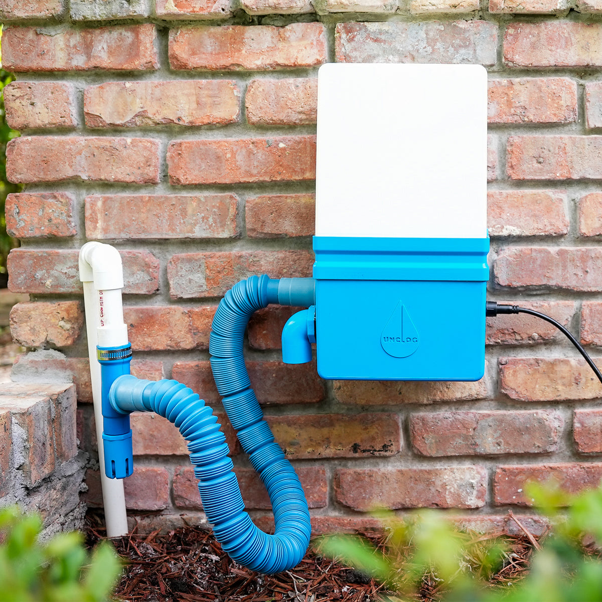
Start with the required pitch, not a rule of thumb
Different equipment and installations can have different drainage requirements. A slope figure is only useful when its source matches the system being reviewed. Keep the equipment model, document revision and relevant instruction beside the calculation.
For context, Carrier’s mini-split drainage guidance discusses a downward gradient of 1:100 for applicable installations. That is an example of source-specific guidance, not permission to apply the same number to every air handler, pump discharge or local installation.
The chart below is arithmetic only. It does not select pipe size, trap geometry, support spacing, venting or the discharge destination. Use the commissioning checklist for the broader verification process.
Condensate drain fall chart: inches per foot
Read the row for the horizontal run and the column for the pitch specified for that segment. Values are total fall in inches. Both columns are examples, not an instruction to choose the smaller value.
| Run (feet) | At ⅛ in/ft | At ¼ in/ft |
|---|---|---|
| 4 | ½ in | 1 in |
| 8 | 1 in | 2 in |
| 10 | 1¼ in | 2½ in |
| 12 | 1½ in | 3 in |
| 16 | 2 in | 4 in |
| 20 | 2½ in | 5 in |
| 24 | 3 in | 6 in |
| 30 | 3¾ in | 7½ in |
| 40 | 5 in | 10 in |
Worked example: a 12-foot segment
If the applicable instruction specifies ¼ inch per foot, the calculation is 12 × 0.25 = 3 inches. If only 2 inches of fall are available, the arithmetic does not meet that specified pitch. A professional must resolve the route; choosing a gentler column does not fix the constraint.
Use the horizontal projection of the segment, not the length of a hose including loops or the total pipe length through vertical drops. Break a complicated route into the relevant segments with your technician.
1%, 1:100 and ⅛ inch per foot are not identical
Percent slope compares fall and horizontal run in the same units. A 1% slope means 1 unit of fall for every 100 units of run. It is exactly 10 millimeters per meter, or 0.12 inch per foot. By contrast, ⅛ inch per foot is 0.125 inch per foot, approximately 1.042%.
| Specified slope | Equivalent | Fall over 20 ft |
|---|---|---|
| 1% or 1:100 | 0.12 in/ft; 10 mm/m | 2.4 in |
| ⅛ in/ft | About 1.042%; 10.417 mm/m | 2.5 in |
| ¼ in/ft | About 2.083%; 20.833 mm/m | 5 in |
Do not round a specified minimum downward. Carry the stated units through the calculation, then discuss practical measurement and installation tolerances with the professional. For a metric example, 6 meters at 10 millimeters per meter gives 60 millimeters of fall.
Enough endpoint fall can still hide a problem
A line can finish lower than it starts while containing a sag or an uphill section between those points. An endpoint calculation cannot establish continuous drainage. Visible support, intermediate elevations and operation all matter.
This worksheet also does not size a pump or determine whether a trap and vent are correct. See the drain-types guide if the route is pumped, shared or uncertain. Do not use a gravity-fall chart as a pump-lift calculation.
For homeowners, the useful next step is a documented question for the technician, not cutting or lifting the pipe. If water is actively leaking or a safety switch is tripping, address that fault first. Unclog does not repair a frozen coil, failed pump, damaged pan or incorrect piping, and it is not an emergency substitute for clearing a blocked line.
Your condensate fall calculation worksheet
Print or copy this section into the job record. Leave unknowns marked “not verified.” A completed calculation is one input to the review, not a commissioning pass.
Equipment model and segment being reviewedInstruction or plan reference, revision and specified pitchHorizontal run and unitsCalculation: run × pitch = total fallAvailable fall, measured by, and measurement dateUnresolved route, support, trap or pump questionsProfessional review and normal-flow verification
Once corrections and normal-flow checks are complete, review the Unclog installation resources and confirm the outdoor termination, mounting, power and complete route. A repeatable suction schedule can then support maintenance of a compatible clear drain.
Review compatibilitySee Unclog’s maintenance featuresCondensate drain slope questions
How much fall is 1/8 inch per foot over 20 feet?
The arithmetic is 20 × 0.125 = 2.5 inches of fall. That result applies only when 1/8 inch per foot is the specified pitch for the segment being reviewed.
Is 1% slope exactly 1/8 inch per foot?
No. One percent is 0.12 inch per foot; 1/8 inch per foot is about 1.042%. Over 20 feet those produce 2.4 inches and 2.5 inches of fall respectively.
Does enough total fall prove my condensate drain is correct?
No. Endpoint measurements can hide sags or uphill sections. Trap, vent, support, pipe size, disposal and operation also need to match the actual installation requirements.
Can Unclog compensate for an uphill drain or a sag?
No. Correct the piping and any active fault, verify normal flow, and confirm compatibility before considering scheduled suction maintenance at the outdoor termination.
Prepared September 22, 2026. Manufacturer context: Carrier mini-split leakage and drainage guidance, reviewed the same day. Chart and worked examples are original arithmetic, not field measurements, installation approval or a claim that one pitch applies to every system.